Key takeaways
- An SFS infill wall is a non-load-bearing cold-formed steel wall built between the floors of a concrete or steel primary frame to form the building envelope.
- Deflection at the head is the central design challenge — the wall must accommodate primary-frame movement without distress.
- Build-up, stud depth and gauge follow from height, wind load and the required fire, thermal and acoustic performance.
- SFS infill is lighter and faster than blockwork and integrates cleanly with cladding and drylining.
SFS Infill Walls: How They Work on Concrete and Steel Frame Structures
In the vocabulary of UK commercial construction, the term ‘infill’ carries a specific structural meaning. An SFS infill wall is not a partition — it is an external envelope element that fills the gap between a building’s primary structural frame and its floors, providing the substrate for insulation, sheathing, and external cladding without contributing to the building’s load-bearing capacity.
This distinction matters. It shapes how infill walls are designed, how they connect to the structure, and what performance requirements they must satisfy. It also determines how they are specified and procured — and why appointing a subcontractor who understands the difference between infill SFS and full-build SFS is important for programme and quality outcomes.
This article explains how SFS infill systems work on both concrete and steel primary frames, the design considerations that govern their specification, and the installation sequence that delivers weather-tightness efficiently. For a broader introduction to Steel Frame Systems in construction, including the range of system types BAS Frames works with, see our overview article.
What Is an SFS Infill Wall?
An SFS infill wall is a non-load-bearing steel framed assembly installed between the slab edges or structural columns of a primary frame — concrete or hot-rolled steel — to close the building envelope at each storey. Unlike a full-build SFS system, which forms the primary structural walls of the building, the infill system’s job is purely to provide a stable, weatherproof, and thermally and acoustically performing facade substrate.
The primary structure carries all gravitational and lateral loads. The infill system carries only its own self-weight and the loads imposed on the cladding by wind pressure and suction. It must also accommodate movement — both thermal expansion and contraction within the steel frame itself, and inter-storey deflection under imposed loads.
An SFS infill wall is a facade engineering component, not a structural one. Its performance is determined by the quality of its connection to the primary frame, its ability to accommodate movement, and the precision of its installation — not by the gauge of its studs alone.
The Primary Structure: Concrete Frame vs Steel Frame
The nature of the primary frame has a direct bearing on how SFS infill is designed and detailed. The two most common primary structures in UK commercial and residential mid-rise construction are reinforced concrete frames and hot-rolled structural steel frames, and they behave differently in ways that matter for infill specification.
Concrete frame buildings
Reinforced concrete frames are the default structure for residential blocks, hotels, student accommodation, and many commercial buildings up to around 20 storeys. The slab edges that define each storey are the fixing datum for infill SFS — head track fixed to the underside of the slab above, sole track fixed to the top of the slab below.
Concrete frame deflection under imposed load is relatively low compared to steel, but it is not zero. The design of the infill head connection must incorporate a slip allowance to accommodate vertical deflection without transferring load into the infill studs. The standard approach is a deflection head detail with a minimum 25mm slip tolerance, increased to 50mm or more where floor spans are long or imposed loads are significant.
Concrete also creeps over time — a long-term deformation under sustained load that is independent of live load deflection. On tall concrete frame buildings, cumulative creep over the building’s life can be significant, and the infill system must be detailed to accommodate it without distress.
Hot-rolled steel frame buildings
Structural steel frames offer greater spans and faster construction than concrete, and are the preferred primary structure for commercial offices, retail, industrial, and mixed-use developments. For a detailed explanation of how hot-rolled steel frame structures work and where SFS systems integrate with them, see our steel frame buildings guide.
Steel frames deflect more under imposed load than concrete frames of equivalent span, and they deflect immediately on load application rather than gradually. The deflection allowance built into the infill head detail must reflect the actual calculated deflection for the specific beam span and loading — not a generic allowance applied across the whole building.
Steel frames also expand and contract thermally across their plan dimensions. In a large commercial building, the horizontal thermal movement at the perimeter of a steel frame over a year can be 20–40mm or more. Infill walls at the building corners and along long elevations must be detailed to accommodate this movement without cracking the board or distorting the framing.
| Factor | Concrete frame | Steel frame |
| Vertical deflection | Lower, gradual (+ creep) | Higher, immediate |
| Thermal movement | Moderate | Greater, especially at perimeter |
| Fixing substrate | Slab edge / column face | Beam flange / column web |
| Deflection head allowance | Typically 25–50mm | Typically 35–75mm+ |
| Programme interface | Post-structure, pre-cladding | Often concurrent with structure |
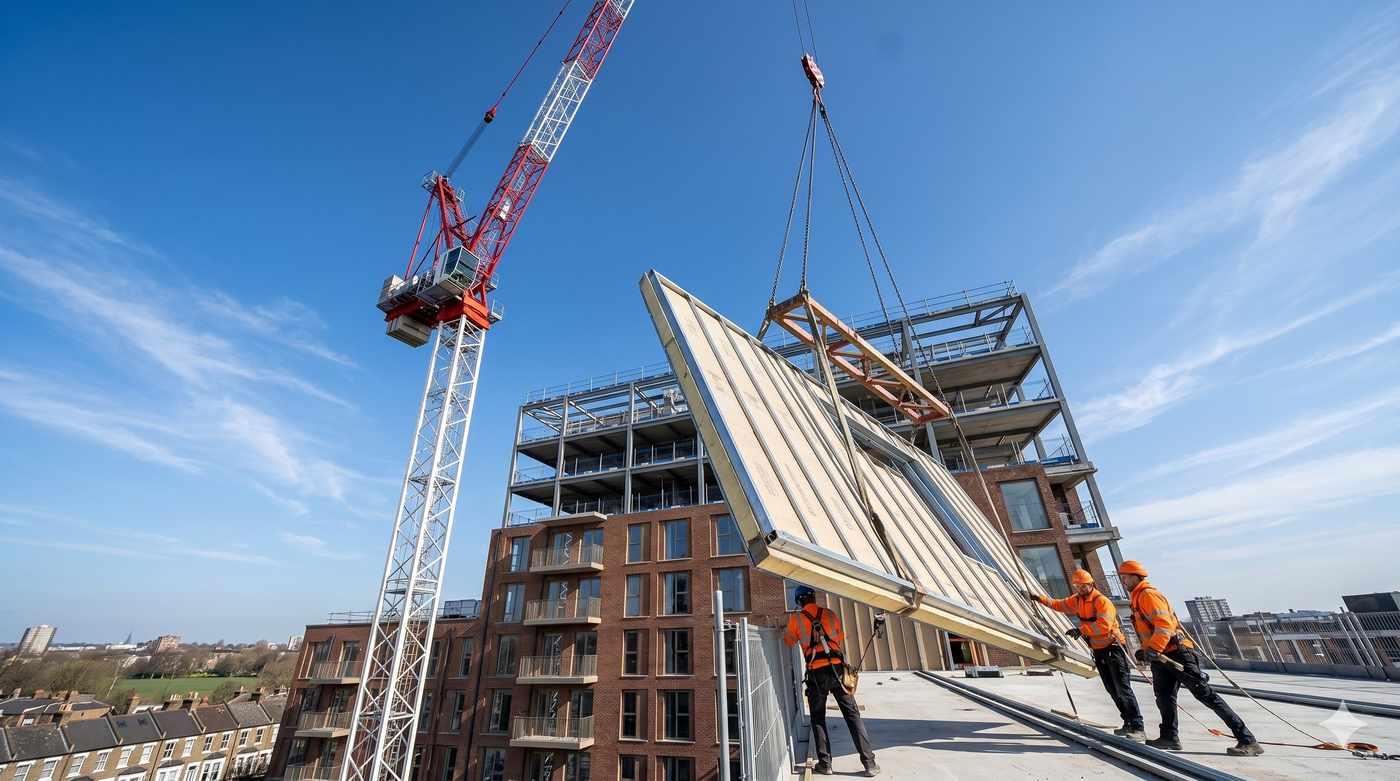
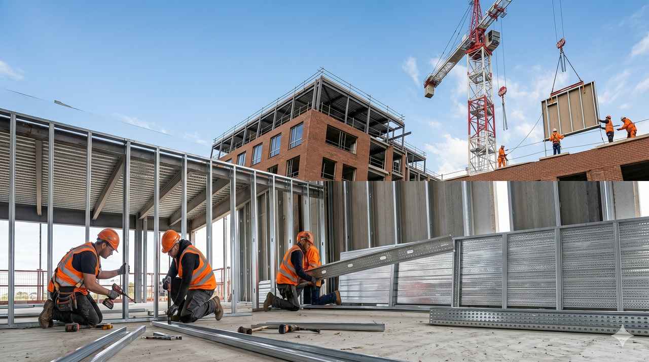
How an SFS Infill System Is Assembled
The assembly sequence for SFS infill follows a consistent logic regardless of the primary structure type, though the specific connection details vary. The key stages are:
1. Setting out and survey
Before any steel is fixed, the infill zone must be surveyed to establish the actual as-built position of the primary structure. In both concrete and steel frame buildings, the structure will deviate from the design drawings within permitted tolerances. Those deviations determine how far each stud will be from the slab edge and what packing or adjustment is required at connection points. A subcontractor who proceeds to installation without a thorough setting-out survey will encounter buildability problems that cost programme and money to resolve.
2. Sole and head track installation
U-track is fixed to the floor slab (sole track) and to the underside of the slab above or beam soffit (head track). The sole track is typically fixed through a continuous or intermittent fixing with a vibration-damping pad where acoustic performance is required. The head track in a deflection detail is fixed to the structural soffit but studs are inserted with a controlled slip tolerance, allowing vertical movement to occur without loading the frame.
3. Stud installation
C-studs are cut to length and inserted between the sole and head tracks at the specified centres — typically 400mm or 600mm depending on the span of the external boarding and the wind load requirements of the façade. On infill systems carrying external cladding, stud gauge and centres are structural design parameters, not arbitrary choices. Where span heights exceed standard manufacturer limits, or where wind loads are elevated, structural engineering input is required to verify the frame design.
4. Opening formation
Window openings, door openings, and service penetrations are formed within the infill frame using jamb studs, cripple studs, and lintel sections. The formation of openings in SFS infill is one of the most technically demanding aspects of the installation — each opening must be correctly framed to transfer wind loads around the void and into the surrounding frame. This is a point where design and installation quality are critical, as the Denham Crematorium project demonstrated: poorly framed or retrospectively modified openings create load path discontinuities that affect long-term performance. See our case study on 2,000m² of SFS delivered under a six-week programme for a real-world account of opening formation in a complex infill installation.
5. Sheathing board installation
External sheathing boards are fixed to the outer face of the stud frame before cladding is installed. Sheathing boards serve multiple functions: they provide racking resistance to the infill frame, they form the substrate for breather membranes and cavity barriers, and in many systems they carry a contribution to the thermal performance of the facade assembly. Board selection — cement particle board, glass tissue-faced board, or magnesium oxide board — is driven by the cladding system and the wind exposure category of the site.
6. Cavity barriers and fire stopping
At every floor level and at specified intervals within the facade cavity, cavity barriers must be installed in accordance with Approved Document B and the project’s fire strategy. This is a statutory requirement, not an optional detail, and it must be completed before cladding installation conceals the cavity. The coordination between infill SFS contractor and the fire-stopping specification is a critical interface — and one that is frequently poorly managed on commercial projects. For the fire performance requirements that apply within the drylining elements of the infill assembly, see our guide to fire-rated drylining for UK commercial projects.
Deflection: The Central Design Challenge
Of all the design considerations in SFS infill specification, deflection accommodation is the one most frequently inadequately addressed. It is also the one with the most direct consequences for long-term performance.
An infill wall that cannot accommodate the movement of the primary structure will transmit that movement as load into the framing, the sheathing board, and eventually the cladding. The visible results are cracked boards, distorted framing, failed sealant joints, and, in extreme cases, water ingress through a façade that appeared weather-tight at practical completion.
The three movement types that the infill detail must accommodate are:
- Vertical deflection — the deflection of the floor or beam above under imposed load, transmitted to the head of the infill frame. Accommodated by a deflection head detail with a slip allowance calculated from the structural engineer’s deflection data.
- Horizontal thermal movement — expansion and contraction of the primary frame in the plane of the facade. Accommodated by expansion joints at regular centres in the infill frame, and by flexible sealant at the interfaces between cladding panels.
- Inter-storey differential movement — relative movement between adjacent floor levels under unequal load distributions. Particularly significant in mixed-use buildings where different occupancy loads apply at different storeys.
The deflection allowance specified in the head detail must be derived from the structural engineer’s calculations for the specific building — not taken from a generic industry default. A 25mm slip allowance is inadequate for a long-span steel frame. The cost of getting this wrong is borne in remediation, not in the original installation.
Thermal and Acoustic Performance of SFS Infill
SFS infill walls must satisfy the thermal and acoustic performance requirements of the building envelope specification, which in a UK commercial building are set by Approved Document L (energy efficiency) and, where residential units are involved, Approved Document E (acoustic performance).
Thermal performance
The thermal resistance of an SFS infill wall is determined by the combined performance of the insulation within the stud cavity, any external insulation layer in the facade build-up, and the contribution of the sheathing board and internal lining. Cold bridging through the steel studs is a significant factor: steel conducts heat approximately 25 times more effectively than a dense mineral wool insulation layer, and in a standard 70mm stud cavity the thermal bridging correction can reduce the effective U-value of the assembly by 20–40% compared to the clear-wall calculation.
The appropriate response is continuous insulation at the external face of the stud frame, outside the thermal bridge. The thickness and position of that external insulation layer is a critical design decision that must be made in coordination with the facade engineer and the structural designer.
Acoustic performance
External SFS infill walls are required to provide a minimum level of sound insulation against external noise, particularly in urban sites where traffic, rail, or aircraft noise is a material consideration. The acoustic performance of the assembly is affected by the mass of the lining boards, the depth of the insulated cavity, and the detail at all perimeter junctions. Where residential accommodation is involved, the requirements of Approved Document E and any planning conditions relating to noise must be addressed at design stage. For acoustic performance within the interior partitions that typically line infill walls from inside, see our guide to metal stud partitions and the acoustic system types available.
SFS Infill vs Alternative Envelope Systems
SFS infill competes primarily with masonry infill and precast concrete panel systems in the mid-rise commercial and residential market. The specification decision between these systems is usually driven by programme, weight, and flexibility of the facade design.
| Factor | SFS infill | Masonry infill |
| Self-weight | Typically 25–45 kg/m² | 200–400 kg/m² |
| Programme speed | Rapid enclosure, 50% faster than masonry | Slower — wet trade, drying time |
| Movement accommodation | Designed in via deflection details | Limited — cracking risk |
| Facade flexibility | Any cladding system compatible | Restricted by fixing requirements |
| Thermal bridging | Managed via external insulation | Inherent mass provides some benefit |
| Height suitability | Up to 18m+ with correct design | Structural limits at height |
| Modification after installation | Openings can be added retrospectively | Demolition required |
The weight advantage is particularly significant in buildings where the primary structure has limited reserve capacity for additional facade load — including many refurbishment and rooftop extension projects. For an overview of how SFS infill systems compare to traditional construction methods more broadly, see our article on steel frame systems vs traditional construction.
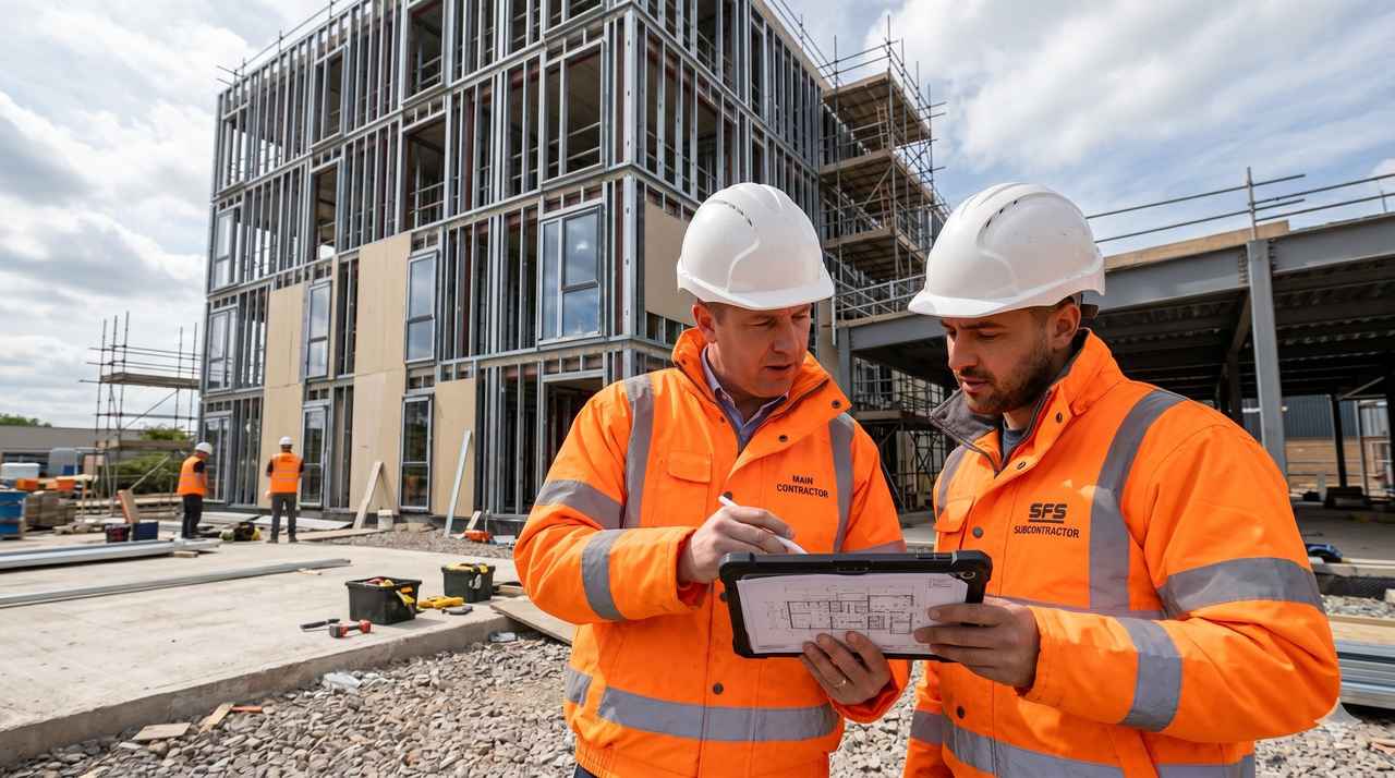
Specifying and Procuring SFS Infill: Key Considerations
A robust SFS infill specification for a commercial project should address the following before the package goes to tender:
- Structural frame type confirmed and deflection data obtained from the structural engineer
- Deflection head detail designed for the specific deflection values, not a generic allowance
- Stud section depth and gauge confirmed by structural calculation for the relevant wind load and height
- Sheathing board type specified to suit the cladding system and wind exposure category
- Thermal build-up designed to achieve the target U-value with cold bridging correction applied
- Cavity barrier positions and specification confirmed against the fire strategy
- Opening framing requirements defined for all windows, doors, and service penetrations
- Expansion joint positions identified for long facades and corners
Procuring SFS infill as a full package — design input, supply, and installation under a single appointment — reduces coordination risk and simplifies accountability. Where the infill package also includes internal drylining, the interface between the external frame and the internal drylining services is managed within one scope rather than across two separate subcontracts.
BAS Frames and SFS Infill Installation
BAS Frames has delivered SFS infill packages across a wide range of commercial, residential, and mixed-use projects in London and the South East. Our infill system capability covers concrete and steel primary frames, buildings up to and beyond 18 metres, and the full range of cladding system interfaces from brick slip to rainscreen.
Each infill project begins with a thorough setting-out survey and a review of the structural engineer’s deflection data before any fixing is designed. Where standard manufacturer details do not address the specific movement or loading conditions of the project, our structural engineering service develops bespoke connection solutions to ensure the infill assembly performs over the life of the building.
For large commercial infill packages, we also provide SFS design input at pre-tender stage, working with the design team to review connection details, identify coordination issues, and produce a buildable specification before the package goes to market. This front-end investment consistently reduces post-contract variation and programme risk.
Conclusion
SFS infill walls are one of the most technically demanding elements of the building envelope. They sit at the interface between the primary structure and the external cladding, and they must accommodate structural movement, satisfy thermal and acoustic performance targets, and maintain fire compartmentation — all in an assembly that is typically less than 300mm thick.
The difference between an infill system that performs over the life of the building and one that begins to show distress within a few years is almost always found in the design and installation of the deflection details, the cavity barriers, and the connection to the primary frame. These are not areas where generic specifications or assumptions about ‘standard practice’ are adequate.
If you are specifying or procuring an SFS infill package on a concrete or steel frame development, contact the BAS Frames team to discuss your project requirements.
Related reading:
→ SFS Infill System — BAS Frames
→ What Are Steel Frame Systems in Construction?
→ Steel Frame Buildings: The Ultimate Guide
→ 2,000m² in Six Weeks: The SFS Delivery Standard
→ Fire-Rated Drylining: Specification Guide
→ Metal Stud Partitions: What They Are and When to Specify Them
→ Steel Frame Systems vs Traditional Construction
Further reading:Steel Construction Institute | Metsec Framing Systems
Related:Cost | What Is | Fire | Thermal
Frequently asked questions
What is an SFS infill wall?
An SFS infill wall is a non-load-bearing external wall constructed from cold-formed steel framing, installed between the floor slabs and columns of a primary structural frame (typically concrete or structural steel). It forms the building envelope — providing weather resistance, thermal performance, fire separation and the substrate for external cladding — without contributing to the structural system.
What is the typical build-up of an SFS infill wall?
A standard SFS infill wall build-up from outside to inside is: external cladding system (rainscreen, brick slip or render), breather membrane, sheathing board (typically cement particle board or OSB), cold-formed steel studs with insulation in the cavity, vapour control layer, and internal plasterboard finish. Cavity barriers are installed at floor levels and around openings.
How tall can an SFS infill wall be?
SFS infill walls can be designed for heights of up to 6–8 metres between structural floor slabs on standard residential schemes. For taller panels — on commercial buildings with high floor-to-ceiling heights — deeper studs (146mm or 200mm) and heavier gauge (1.2mm or 1.6mm) may be required, with the design confirmed by a structural engineer. Wind load is the governing design parameter for tall infill panels.
What fire rating does an SFS infill wall achieve?
SFS infill walls with appropriate sheathing and internal lining can achieve external fire resistance ratings of EI-60, EI-90 or EI-120 depending on the system specification. The complete external wall assembly — including the cladding system — must be assessed for fire performance on buildings over 18 metres. BAS Frames works with fire engineers and cladding specialists to ensure compliant specifications.